Arduino heeft twee nieuwe ontwikkelkits voor IoT-toepassingen gelanceerd. Een ervan maakt voor het eerst gebruik van een FPGA-chip voor extra flexibiliteit. Arduino wil met beide kits zijn portfolio verder uitbreiden om de zogenaamde ‘Maker’-groep te kunnen bedienen.
Arduino heeft twee nieuwe ontwikkelkits beschikbaar gesteld voor IoT-toepassingen: Vidor 4000 en Uno Wifi Rev2. Vooral de Vidor 4000 is een heel interessante kit omdat het gebruik maakt van een FPGA-chip van Intel. Het is de allereerste keer dat Arduino de chip integreert in één van zijn kitjes. Het voordeel van FPGA is dat de chip helemaal zelf kan worden geprogrammeerd zodat er het maximale uit kan worden gehaald.
FPGA-chip
Microsoft gebruikt FPGA-chips in Azure voor AI-toepassingen, maar de chip kan nog veel meer. Arduino wil nu in de DIY-community aftasten wat iedereen met deze chip zal doen en noemt het zelf de interessantste toevoeging in jaren aan zijn line-up.
Verder is er de Uno WiFi Rev2-kit, een IoT-bordje met een verbeterde AVR-microcontroller van Microchip. Belangrijkste vernieuwing is de verbeterde centrale processor met meer computerkracht en geheugen om IoT-applicaties te draaien.
Beide kitjes zijn nog niet beschikbaar, maar je kan je online registreren om een melding te krijgen wanneer ze leverbaar zijn.
IoT-boom
Arduino wil met beide kitjes mee genieten van de IoT-boom in technologieland. Het laat aan IoT Institute weten dat de nieuwe ontwikkelkits niet de huidige industriële apparatuur vervangt. Arduino ziet het eerder als een toevoeging voor een bestaand systeem waar ze meer willen doen met de data dan nu mogelijk is. Die data willen ze begrijpen, analyseren en wanneer er fouten zijn willen ze daarop kunnen reageren. Dat is de toepassing waarop Arduino mikt met de nieuwe kitjes.
https://www.okystar.com/wp-content/uploads/2018/07/arduino.jpg456927adminhttps://okystar.com/wp-content/uploads/2017/05/okystar-logo.pngadmin2018-07-24 08:13:412018-09-18 09:18:53Arduino introduceert twee nieuwe IoT-ontwikkelkits
After Hongkong Electronic on Oct.2017,Okystar has taken part in Bett Excel Education Show as Exhibitor.In this time,gladly we are willing to invite each VIP clients to our booth.
Aim to improve the child’ and adults Electronic programming ability,many new manuals have been provided and customized with different users.
In this time,some new products around arduino,raspberry PI,microbit,which will be showed in our booth.Firmly believe it is the useful for school teacher,students in science class.
What is changing?
Transformation Study surveyed 1494 business leaders from Asia Pacific that included 265 respondents form higher education institutions. It found 87 percent agreed that educational institutions need to become digital to increase growth. It was found 76 percent institutions in Asia are already in various stages of strategic processes.In this case,we need to improve the Electricity learing.
More and more students would like to get more knowledge by science experiment.That means as a guider of science education area,it is necessary to creat some light and new DIY Kits.At the same time,stronged our board,sensor is our target too(Developing more function with high technology).
Learning with games
Our Smart car,arduino starter kit,DOF robot serious are taking a role as friendly-game.Enriched programmable DIY system,which make many students get a new favor as closed partner in Leisure time.All DIY experiment has gotten the offical approval from China government.Because of environmentally friendly materials, all parents can rest assured their children’s safety.
Why educators need to be a part of it?
The future of education sees one massive constant: change. Nothing is set to remain as it were. Students will no longer have to lug around huge backpacks full of books. Instead they will get by with everything on an 8mm thick tablet connected to the world. Distance and time become relative as everyone, everywhere can access education tailored to their needs and skills. This is not science fiction anymore but a solid reality. Considering how big our youth population, it is imperative to adapt and adopt better learning technologies.
https://www.okystar.com/wp-content/uploads/2017/12/2018年邀请涵-1.jpg500800adminhttps://okystar.com/wp-content/uploads/2017/05/okystar-logo.pngadmin2017-12-25 03:56:232018-05-21 02:01:14UK London BETT Excel Education Show - Okystar
Delay statements are great and all, especially for their simplicity, but they can really put a damper on things when trying to multitask your Arduino. Forget delay and hop on the millis() train!
It’s pretty easy to just throw in a delay statement whenever you need your microcontroller to pause briefly, but it’s a real bummer when you are trying to do other things, like monitor a button push. As my Arduino skills have improved, I figured it was time to drop the delay and learn to be able to multitask my Arduino. Yes, it does add a bit more code to your programs, but it, in turn, makes you a more skilled programmer and increases the potential of your Arduino. To do so, we will need to learn how to use the “millis()” command.
How?
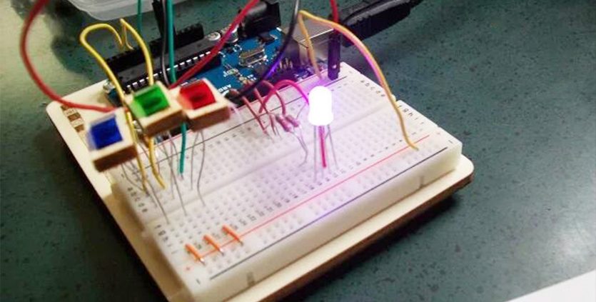
You see, delays pause your Arduino’s program, making it incapable of doing anything else in that time period. Instead of pausing our entire program for a specified time, we will learn to count how much time has passed before completing an action. This, of course, is accomplished with our good friend “millis()” and a few variable friends to store our data. To make things easy, we’ll start with everybody’s first sketch, “Blink,” but instead we will “Blink without Delay.”
First begin like any other program, declaring any necessary pins or variables, such as your LED on pin 13. We’ll also need an integer to store the current state of the LED. This will be set to LOW as the initial LED state is off. Then declare a variable “previousMillis” of type “unsigned long.” Instead of using “int,” unsigned long variables are 32 bits, for variables whose value can become very large—like the potential amount of time we may want to wait until an action is taken.
“previousMillis” will be used to store the last time our LED blinked. “const long” is also 32 bits but will never change, or is constant. We will set this to 1000 and use it as our pause time, measured in milliseconds because we always want to pause for 1000ms. Then, of course, remember to declare your pinMode for your LED as usual.
// constants won't change. Used here to set a pin number :constint ledPin = 13; // the number of the LED pin// Variables will change :int ledState = LOW; // ledState used to set the LED// Generally, you should use "unsigned long" for variables that hold time// The value will quickly become too large for an int to storeunsignedlong previousMillis = 0; // will store last time LED was updated// constants won't change :constlong interval = 1000; // interval at which to blink (milliseconds)voidsetup(){
// set the digital pin as output:
pinMode(ledPin, OUTPUT);
}
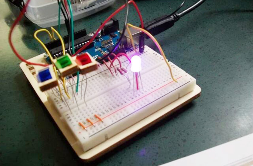
Then we move onto the loop! Remember, instead of delaying, we want to count how much time has passed since our last blink, in our case, 1000ms. If the stated time has passed, it’s time to change the state of our LED, either from off to on or vice versa.
First, we will set the unsigned long “currentMillis” equal to “millis()” which places the current time count in millis. This will help us determine if the difference between current time and previous time has surpassed 1000ms. To do so we say, “if current time minus the previous time our LED blinked is greater than or equal to our assigned value of 1000ms, store the time of the most recent blink as previousMillis.” This will help us remember how long it’s been since the last blink the next time around the loop.
Then, if the LED state is LOW, make it HIGH, else, make it LOW. Then digitalWrite the LED HIGH or LOW depending on the previous state.
voidloop(){
// here is where you'd put code that needs to be running all the time.// check to see if it's time to blink the LED; that is, if the// difference between the current time and last time you blinked// the LED is bigger than the interval at which you want to// blink the LED.unsignedlong currentMillis = millis();
if (currentMillis - previousMillis >= interval) {
// save the last time you blinked the LED
previousMillis = currentMillis;
// if the LED is off turn it on and vice-versa:if (ledState == LOW) {
ledState = HIGH;
} else {
ledState = LOW;
}
// set the LED with the ledState of the variable:
digitalWrite(ledPin, ledState);
}
}
Remember to take it slow and break down the code into smaller sections that you can more easily understand. If you don’t get it just yet, that’s okay—it takes some practice. If you do understand it and get it working, try adding in a second LED to the mix and get them blinking at different rates. More information on this subject can be found on Adafruit Industries website, where Bill Earl has provided a three-part series on multi-tasking your Arduino—even adding motors and addressable LEDs to the mix so check it out! Thanks again for following along!
https://www.okystar.com/wp-content/uploads/2017/11/arduino-uno-r3.png438781adminhttps://okystar.com/wp-content/uploads/2017/05/okystar-logo.pngadmin2017-11-03 00:58:092018-05-21 02:01:45Uno Multitasking! How to Use Milli in Uno R3 Code
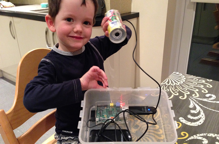
For children and teens interested in robotics and programming, an Arduino starter kit is an excellent way to begin.
What exactly is Arduino? Simply put, Arduino is an open-source platform used for building and programming electronics projects. Projects range from incredibly simple to very complicated. Arduino refers to two things. First, the actual programmable circuit board, or microcontroller. Second, it refers to the computer software used to program and control the device.
There are a few things to consider when choosing an Arduino starter kit. Perhaps most importantly, it should include some sort of manual or instructions. In the beginning, starting with Arduino can be a bit daunting, and clear instructions will help young makers get started. Also, a basic kit should include an Arduino control boards and enough components for at least a few projects. Arduino is the perfect platform for beginning electronics and these kits will help your youngster get started in the exciting world of programming.
Starter Kit Options for Kids and Teens
1. Official Starter Kit for arduino
The Official Starter Kit for arduino offers everything young makers and programmers need to create 15 fun projects. This kit includes the Arduino UNO, the most recent Arduino control board. In addition, it has all of the essential components like the control board, lights, buttons, switches, resistors, and more. Additionally, it features a detailed 170 page with instructions. Projects include a lamp that works with touch controls, a mystical crystal ball, a knock lock that allows the user to open a door with a secret code, a musical keyboard, and more. This is a well-appointed kit for beginners.
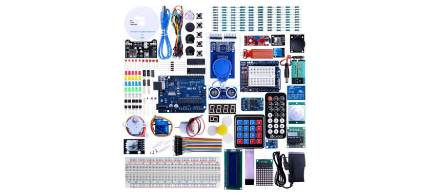
2. UNO R3 Project Complete Starter Kit
The UNO R3 Project Complete Starter Kit includes more than 200 components and 63 Arduino specific products. It features the Arduino UNO R3 controller board. As an added bonus, all of the modules are pre-soldered and connect easily. This is an excellent feature when considering a kit for children and teens. Download the free PDF tutorial with 30 Arduino building and programming lessons and project ideas. This kit also includes a helpful CD with necessary codes. The entire kit is stored in a convenient container with divided compartments for smaller components.
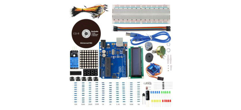
3.UNO Project Basic Starter Kit
The UNO Project Basic Starter Kit is a great Arduino starter kit for beginning programmers. It includes more than 140 components for creating unique Arduino projects. Featuring the latest Arduino UNO R3 controller board, this kit also includes an LCD 1602 screen and an 830-hole breadboard. Also, a servo motor SG90, temperature and humidity sensor, potentiometer, thermistor, and 8*8 LED matrix. The included CD has a 23 project tutorial with necessary software and source code. Additionally, the kit comes packaged in a convenient storage container.
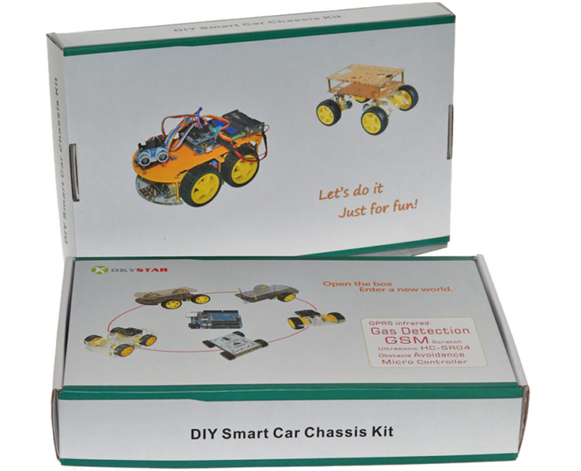
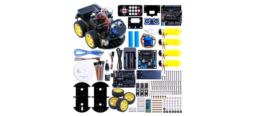
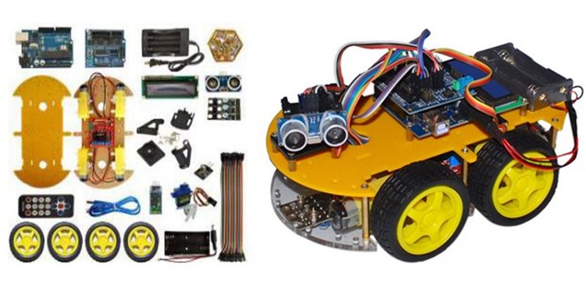
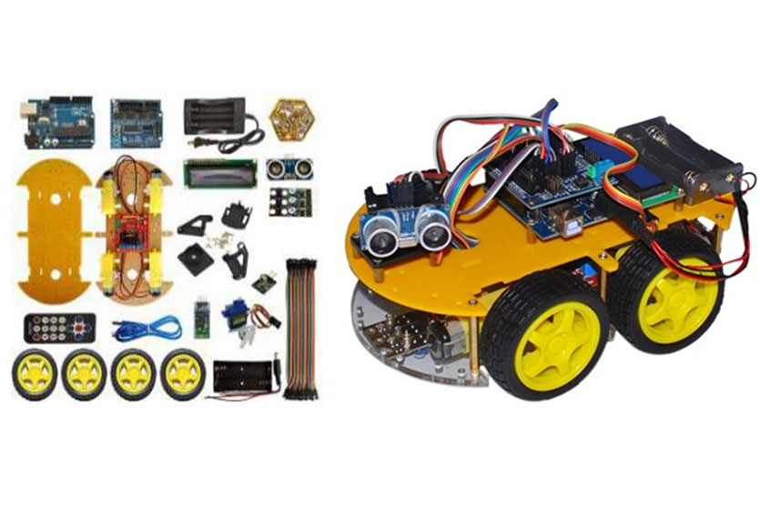
4. UNO Project Smart Robot Car Kit
Construct and program a cool remote controlled smart car with the UNO Project Smart Robot Car Kit. Build your smart car and install the programmable Arduino UNO R3 control board. After it’s built and programmed, control the car with the included IR remote. Or, use the included CD to install and smartphone app and control the car with Bluetooth. The kit includes all of the components required and reviewers report that this kit is appropriate for Arduino and robotics novices.
More details please contact with the team of Okystar!
The jaycar project is an open-source platform used for building electronics . It consists of both a physical programmable circuit board (often referred to as a microcontroller) and a piece of software, or IDE (Integrated Development Environment) that runs on your computer, used to write and upload computer code to the physical board.
The platform has become quite popular with people just starting out with electronics, and for good reason. Unlike most previous programmable circuit boards, the it does not need a separate piece of hardware (called a programmer) in order to load new code onto the board – you can simply use a USB cable. Additionally, the IDE uses a simplified version of C++, making it easier to learn to program. Finally,jaycar electronic,funduino provides a standard form factor that breaks out the functions of the micro-controller into a more accessible package.
https://www.okystar.com/wp-content/uploads/2017/05/blog4-0.jpg550835tinahttps://okystar.com/wp-content/uploads/2017/05/okystar-logo.pngtina2017-05-24 11:34:162017-12-27 05:58:59What Is This Project?
The Arduino Robot is the first official Arduino on wheels. The robot has two processors, one on each of its two boards. The Motor Board controls the motors, and the Control Board reads sensors and decides how to operate. Each of the boards is a full Arduino board programmable using the Arduino IDE.
Both Motor and Control boards are microcontroller boards based on the ATmega32u4 (datasheet). The Robot has many of its pins mapped to on-board sensors and actuators. Programming the robot is similar to the process with the Arduino Leonardo. Both processors have built-in USB communication, eliminating the need for a secondary processor. This allows the Robot to appear to a connected computer as a virtual (CDC) serial / COM port. As always with Arduino, every element of the platform – hardware, software and documentation – is freely available and open-source. This means you can learn exactly how it’s made and use its design as the starting point for your own robots. The Arduino Robot is the result of the collective effort from an international team looking at how science can be made fun to learn. Arduino is now on wheels, come ride with us!
You can find here your board warranty informations.
Communication
The Robot has a number of facilities for communicating with a computer, another Arduino, or other microcontrollers. The ATmega32U4 provides UART TTL (5V) serial communication, which is available on digital the 10-pin board-to-board connector. The 32U4 also allows for serial (CDC) communication over USB and appears as a virtual com port to software on the computer. The chip also acts as a full speed USB 2.0 device, using standard USB COM drivers. On Windows, a .inf file is required. The Arduino software includes a serial monitor which allows simple textual data to be sent to and from the Robot board. The RX (LED1) and TX LEDs on the board will flash when data is being transmitted via the USB connection to the computer (but not for serial communication between boards). Each one of the boards has a separate USB product identifier and will show up as different ports on you IDE. Make sure you choose the right one when programming. The ATmega32U4 also supports I2C (TWI) and SPI communication. The Arduino software includes a Wire library to simplify use of the I2C bus; see the documentation for details. For SPI communication, use the SPI library.
Programming
The Robot can be programmed with the Arduino software (download). Select “Arduino Robot Control Board” or “Arduino Robot Motor Board” from the Tools > Board menu. For details, see the getting started page and tutorials.
The ATmega32U4 processors on the Arduino Robot come preburned with a bootloader that allows you to upload new code to it without the use of an external hardware programmer. It communicates using the AVR109 protocol. You can bypass the bootloader and program the microcontroller through the ICSP (In-Circuit Serial Programming) header; see these instructions for details.
Automatic (Software) Reset and Bootloader initiation
Rather than requiring a physical press of the reset button before an upload, the Robot is designed in a way that allows it to be reset by software running on a connected computer. The reset is triggered when the Robot’s virtual (CDC) serial / COM port is opened at 1200 baud and then closed. When this happens, the processor will reset, breaking the USB connection to the computer (meaning that the virtual serial / COM port will disappear). After the processor resets, the bootloader starts, remaining active for about 8 seconds. The bootloader can also be initiated by double-pressing the reset button on the Robot. Note that when the board first powers up, it will jump straight to the user sketch, if present, rather than initiating the bootloader.
Because of the way the Robot handles reset it’s best to let the Arduino software try to initiate the reset before uploading, especially if you are in the habit of pressing the reset button before uploading on other boards. If the software can’t reset the board you can always start the bootloader by double-pressing the reset button on the board. A single press on the reset will restart the user sketch, a double press will initiate the bootloader.
USB Overcurrent Protection
Both of the Robot boards have a resettable polyfuse that protects your computer’s USB ports from shorts and overcurrent. Although most computers provide their own internal protection, the fuse provides an extra layer of protection. If more than 500 mA is applied to the USB port, the fuse will automatically break the connection until the short or overload is removed.
Physical Characteristics
The Robot is 19cm in diameter. Including wheels, GTFT screen and other connectors it can be up to 10cm tall.
https://www.okystar.com/wp-content/uploads/2017/05/Robot-for-arduino1.jpg557835tinahttps://okystar.com/wp-content/uploads/2017/05/okystar-logo.pngtina2017-05-17 10:54:372017-05-25 01:19:51Robot For Arduino