Maker UNO Simplifies Arduino,less cost

The engineers at Cytron Technologies worked with educators at the Arus Academyin Selangor, Malaysia to develop a better Arduino tool. As a teaching tool they felt that current Arduino boards were too difficult for students with no existing knowledge of electronics. Circuit diagrams at the beginning of lessons required several connections and much of the time was spent troubleshooting wires and contact points. At the end of the lesson teachers had to sort through all of the kits and make sure that no components were left out of the boxes for the next lesson. Their solution is the Maker UNO, an Ardiuno compatible system for education that simplifies electronics and coding for students while making troubleshooting easier for educators.


https://www.kickstarter.com/357b5ea2-6149-4516-b1bc-f3a7b481e3af


The Maker UNO incorporates twelve LEDs into the board to act as a troubleshooting array and take some of the basic electronics out of the assembly process. Their basic idea was to build a mechanism that could break down problems into a connection issue or a coding issue. Maker UNO works with micro USB cable and its carrying case has a plug cutout for use. The ATmega328P microcontroller on the board runs at 16 MegaHertz and 5 Volts. An on-board piezo buzzer and programmable button are also included, along with a switch to mute the buzzer (most middle schoolers’ favorite part of any electronics kit, I’ve learned, is trying to make the buzzers and beeps as loud as possible.) The main differences between the Maker UNO board and a straight Arduino Uno board are the twelve LEDs, buzzer and button, and the removal of a DC power input socket. Maker UNO also uses a CH340 bus convert chip to save costs. Incredibly, the group hopes to sell these boards for $6 each after the Kickstarter campaign is over.
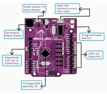
 

This is the first I’ve heard of Arus Academy but as in institution they have a strong commitment to STEM learning. The group has sponsored many activities in the past including Maker Academy, Girls in Engineering / Math / Science (GEMS), Math / Information / Data Science (MINDS),  and Design / Art / Robotics / Engineering (DARE).  There are already two curriculum pieces in place for the Maker UNO boards, one with lots of graphics written in English and one more command and text based written in Malay. The campaign has completely blown past its modest $3500 goal and will end on April 17. First units have an estimated delivery date of June 2018.


Designing an Arduino-powered split-flap display Create a coffee notification system

Posted by:ARDUINO TEAM — February 22nd, 2018

Moscow-based artist ::vtol:: is back again with an interesting interactive exhibit entitled “you, me and all these machines.” His latest work, a collaboration with Lovozero, allows two participants to produce otherworldly vocals together.

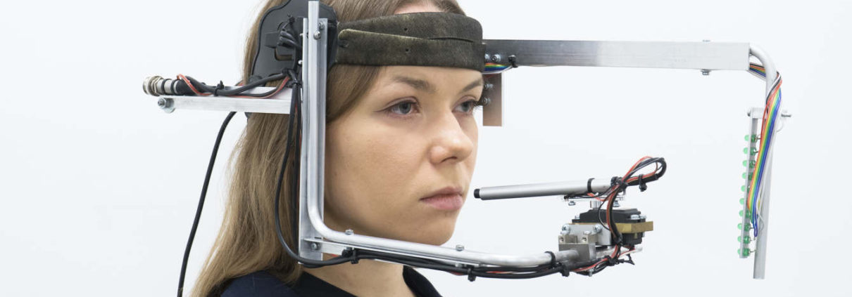
One participant wears the device, which points a directional microphone under the control of the other participant at her mouth using a servo motor. An array of LEDs signal the vocalist in a manner agreed upon before the performance.

 
The head-mounted system is controlled by an Arduino Uno, and is meant to display the subtle interaction between two participating artists, as they must work together to produce the desired output.

“You, me and all these machines” is a performance for voice and electronic devices. The vocalist puts on his or her head a specially designed wearable interface tool to interact with the voice and display a visual score. Technically, the device consists of several elements: a narrowly directional microphone driven by a motor; an LED strip that shows the vocalist score; remote control with a joystick used by the second participant to control the interface.

Shifting the microphone against the mouth makes it possible to achieve interesting sound effects, and makes it easier to manipulate the vocalist’s voice. The LED line consisting of 10 diodes is a very primitive, but effective and convenient way of interacting with the vocalist, and the way of interpreting the values is predetermined before each performance. During the performance, a sound canvas is formed, thereby changing the dynamics, consisting of a set of looped fragments created within voice and interface processing elements, without using other methods to generate sounds.

Check out “you, me and all these machines” in the video below!

Playing chiptunes on an old reed organ with Arduino

Posted by:ARDUINO TEAM — January 3rd, 2018
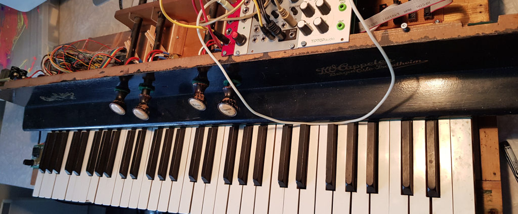
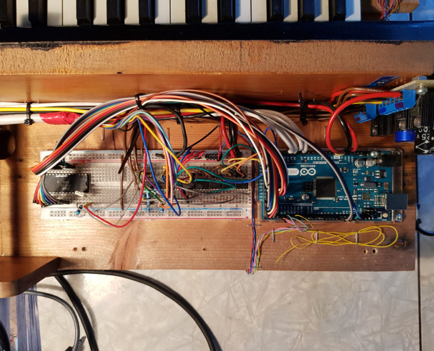
After finding an organ left outside to rot, hacker “tinkartank” decided to use it for his own purposes, adding push buttons under each key as inputs to an Arduino Mega.

He also reused the control rods with potentiometers as a secondary input method, and added a tiny OLED to display the system’s menu. With this unique interface setup, the Mega drives a MOS6581 SID chip—originally used to produce sound on the Commodore 64—for music generation, and can interface with Eurorack modules as needed.

Want to see more? Be sure check out the SID organ in action below, and read the entire project write-up here.

ESP Alarm: Make an IoT, Wi-Fi Enabled Alarm Clock with an ESP8266

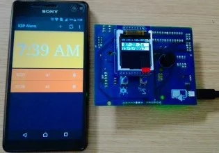
The “ESP Alarm” is a connected alarm with your smart phone via Wi-Fi using ESP8266 module. You can add/modify/delete/activate/deactivate alarms using an Android application when the device is up and connected with the same Wi-Fi network which your phone is connected to.

It’s common to set-up alarms using our mobile phones to wake up in the morning—and it’s not unusual to set-up several alarms in an attempt to wake up at a specific time. The problem is that, after we finally wake up, sometimes our phone’s battery is drained during the battle to get up from bed!

So I decided to make an “ESP Alarm” device that allows me to set alarms using my smartphone through Wi-Fi and leave the rest to the alarm clock. In simple terms, it’s a Wi-Fi-enabled, IoT alarm clock!

This is my second project using the tiny monster ESP8266 Wi-Fi module. Check out my first project, “How to Build a Control Circuit with Adjustable Working Time via Wi-Fi” here on AAC.

Important Notes

  1. This application requires Android 4.4 (Marshmallow) and up.
  2. The maximum number of alarms is 20 due to hardware limitations.
  3. This app is under development and still missing some enhancements, but it meets the main requirements for this project.

Many thanks to my friend Jihad Al-bathish (AKA Joud) for developing a native Android application for this project.


Overview of the Device

ESP Alarm Schematic


ESPAlarm Schematic

Click to enlarge


BOM

Part Documentation QTY
Arduino UNO or any compatible board (optional) https://www.arduino.cc/en/Main/ArduinoBoardUno 1
ATmega328P (optional) www.atmel.com/devices/ATMEGA328P.aspx 1
ESP8266 Wi-Fi module, ESP-01 model www.esp8266.com/wiki/doku.php?id=esp8266-module-family 1
1.44-inch TFT display module https://world.taobao.com/item/521610992161.htm 1
TP4056 breakout board (Li-ion battery charger) https://world.tmall.com/item/38825413372.htm 1
DS1307/ DIL-08 package (RTC chip) https://www.maximintegrated.com/en/products/digital/real-time-clocks/DS1307.html 1
74LVX4245/ TSSOP-28 package (5V-3V3 level converter) https://www.fairchildsemi.com/products/logic/voltage-level-translators/voltage-level-translators/74LVX4245.html 1
USB TTL converter cable (optional) http://www.ftdichip.com/Products/Cables/USBTTLSerial.htm 1


The “ESP Alarm” is connected with an Android application via Wi-Fi using the ESP8266 module. You can add/modify/delete/activate/de-activate alarms using the Android app when the device is up and connected with the same Wi-Fi network your phone is connected to.

My “ESP Alarm” has a 1.4-inch TFT screen and two buttons as a user interface. One button is used to turn off the alarm and the other is to snooze it. The welcome message (for when the user turns the alarm on) and the snooze time are settable through the app. Time and date are shown on the TFT screen and synchronized with your phone’s time/date.

Changing or adding new alarms can be done with a handshake process. This means that, if the app didn’t receive a response from the device, then it will not do the desired action. We decided to add this restriction to avoid any mis-synchronization problems between your smartphone and the “ESP Alarm”.

Alarms can be set to be one-time-only or repeatable (based on the day). Each one has a unique title shown on the TFT screen when it goes off (so you can remind yourself of specific appointments, recurring meetings, etc.).


Hardware

The ESP8266 is connected with an Arduino UNO via UART connection using AT command (commands in ASCII). You can add/modify/delete/activate/deactivate alarms using the Android app when the device is up and connected with the same Wi-Fi network your phone is connected to.

I used a 1.4-inch TFT screen to print out some important information like time, date, IP address, port number, title of the alarm, etc. Both the TFT screen and Wi-Fi module use 3V3 logic level and need a level converter with Arduino which uses 5V logic level.

Time and date are kept in the RTC chip, DS1307, which is connected with Arduino using an I2C interface. I added a Li-ion backup battery to maintain a correct date and time even if the device is turned off. To charge this battery, I used a charger IC called TP4056.


TFT Screen

I used a 1.44-inch, 128×128 resolution, SPI TFT with an ILI9163C internal driver. These modules come in two versions, one with a 3V3-5V on-module level converter IC and another one without this IC.

1.44 SPI TFT Module Versions

1.44″ SPI TFT module versions


I bought one of the 3V3 modules from a Chinese supplier but, for some reason, I received the 5V version instead of the 3V3 version.

Anyway, I added an external level converter IC which is 74LVX4245. It’s an 8-bit translating transceiver that is designed as an interface between a 5V bus and a 3V bus in a mixed 3V/5V supply environment. This IC has 8-pin A port for 5V logic, an 8-pin B port for 3V logic, and a Transmit/Receive (T/R#) input pin to determine the direction of data flow (from A to B or B to A). In my case, I fixed the direction from A (5V) to B (3V3).

To interface with this TFT module, you need to add the TFT_ILI9163C library (written by Sumotoy) to your Arduino IDE and to connect the TFT pins with Arduino as follows:


Pin From TFT Pin From Arduino Note
VCC +3V
LED +5V through a resistor The module has a current-limiting resistor but I found it’s safer to add another one with low value such as 100 – 1K ohm.
GND GND
SCL (SPI Clock) PIN 13 SCL is not related to the “SCL” pin in I2C protocol. The datasheet of ILI9163C used the same abbreviation.
SDA (SPI MOSI) PIN 11 SDA is not related to the “SDA” pin in I2C protocol. The datasheet of ILI9163C used the same abbreviation.
D/CX PIN 9 (optional) Display data / Command selection pin
CS PIN 10 Chip Select
RES +3V Reset


Another important thing about this TFT is to know how to format a color. This TFT controller supports 18-bit, 16-bit, and 6-bit RGB interfaces. Sumotoy’s library uses 16-bit RGB format.


RGB565


This is known as RGB565 (5 bit red, 6 bit green, and 5 bit blue). There are some online tools that can give you your color of choice in this format.


Wi-Fi Module

The ESP8266 is a low-cost SoC chip with an embedded microcontroller and a full TCP/IP protocol stack, which means that it can directly access your Wi-Fi network. Because this chip has its own MCU, you can put your application code within it or you can use the module just as a Wi-Fi transceiver—like what we are going to do in this project. This is done using AT command (again, commands in ASCII) using a UART connection. You can view the full list of AT commands in this document.


ESP8266 ESP-01 Model Pinout

Image taken from the ESP8266 Wi-Fi Module Quick Start Guide


The ESP8266 chip comes in different module models but we’ll use the ESP-01 model.


The module uses the 3V3 level, so we need to do a conversion between it and the Arduino, which uses the 5V level. Since we already used four pins of the 8-pin port from 74LVX4245 converter IC for the TFT screen, we’re going to use a fifth pin to convert the TX signal from the Arduino to 3V3 level.

The TX signal from the ESP8266 can be left without any conversion to 5V as long as the minimum input-high voltage at VCC = 5V is about 2.65 V according to Figure 35-25 from the ATmega328P’s datasheet (the Arduino UNO’s controller).


Image taken from the ATmega328P datasheet


However, in the same datasheet, (Table 30-1) the lowest value where the pin is guaranteed to be read as high is 0.6×VCC= 0.6×5 =3V. Also, according to (Table 5-1) in the ESP8266EX datasheet, the minimum output-high voltage is 0.8×Vio = 0.8×3.3 = 2.64V which is a little bit smaller than the minimum input-high voltage of ATmega328.

So the connection could be unreliable in the worst case. I decided that it’s safer to convert from the 3V level to 5V using a simple circuit comprised of one MOSFET and two pull-up resistors:


 5V-3.3V Bidirectional Level Converter

5V-3.3V bidirectional level converter


RTC Chip

DS1307 is the RTC chip used to get time from its internal non-volatile registers while there is a power supply or a backup battery. This IC uses an I2C interface with its MCU which consists of two lines: SCL (Serial Clock) and SDA (Serial Data). I used a library called DS1307RTC to deal with it on Arduino, which you can get from the PJRC website.

I used a Li-ion battery (from my old phone, the NOKIA C5) with a TP4056, a complete constant-current/constant-voltage linear charger for single cell lithium-ion batteries. Just to make things easier, I used a breakout board like the one in the photo.


TP4056 Breakout Board

The TP4056 breakout board. Image source: HAOYU Electronics


You can change the charging current by changing the resistor Rprog value. For more information, please refer to the charger’s datasheet.


Arduino Code

The code depends on the following libraries:

  • TFT_ILI9163
  • Adafruit_GFX
  • DS1307RTC
  • Wire (for I2C connection)
  • EEPROM (to store alarms in the internal EEPROM)
  • SoftwareSerial (optional debugging)

First, the code initializes an SPI connection with the TFT screen, an I2C connection with the RTC chip, and a UART connection with the Wi-Fi module. Then it prints an intro screen which includes the AAC logo (I tried to match it with the original one as much as possible!).

The Wi-Fi module must be configured with your network SSID/password and other settings, like your port. You must change this part:


sendCommand("AT+CWJAP=\"YOURSSID\",\"YOURPASSWORD\"\r\n", 1000, DEBUG);


Note: Make sure to wait about six seconds (delay(6000);) after that because the module needs some time to connect to the network.

If everything works, your module will obtain an IP using this command:


IP = sendCommand("AT+CIFSR\r\n", 1000, DEBUG); 


Checking the Obtained IP

I added a simple method to check the obtained IP.

Usually, for a local connection with your router, the IP will be something like 192.168.1.100. The response from the module for this command “AT+CIFSR” will be something like:

+CIFSR:STAIP,”192.168.1.50″

+CIFSR:STAMAC,”18:fe:34:9f:48:d8″

And if the connection is failed, the response will be:

ERROR

So I found that the simplest way to find an error is to check the length of the response.

Note: I get the IP from the response using the substring function of the String object IP between characters 25 and 38. The response starts with AT+CIFSR\r\n+CIFSR:STAIP,” which is 25 characters


IP = sendCommand("AT+CIFSR\r\n", 1000, DEBUG); // get ip address
  if (IP.length() <= 25)
  {
    IP = "NOT Avaliable";
    tft.print(" Not \r\n Connected :(");
    return 0;
  }
  else
  {
    IP = IP.substring(25, 38); // Get the IP part from the command response
    tft.print("Connected ");
    return 1;
  }


Communication Commands

The communication commands received from the mobile application and the expected corresponding responses from the Arduino side are shown in this table:


Command Response Note
SET CT Setting the snooze time and welcome message. Example: SET,5,Hello;
ADD AT Adding an alarm.
ADD,ID,A(active)/D(deactive),HHMM,RepDays,SoundType,Title;
DEL DT Deactivating/deleting an alarm
SYN ST Syncing the time between the RTC chip and your mobile. SYN,DD+MM+YYYY,HH:MM:SS, Example: SYN,08+20+2016,09:28:56,1
DEB No response Printing some internal information on the screen.
RES RT Resetting the alarm, including flashing the internal EEPROM.


To keep alarms saved even when you turn off the device, I used the internal EEPROM which is not the best choice because it has a limited number of times to read/write its contents. The EEPROM has an endurance of at least 100,000 write/erase cycles. I think it’s better to use external memory in a future development.

The memory structure is simple. 22 bytes for every alarm, as follows:

  • B0:ID-B1:A(Active)/D(Deactive) as char
  • B2:HH(Hour) as number
  • B3:MM(Minuit) as number
  • B4:Rep Day as number interpreted as flags
  • B5:reversed
  • B6..B21: Title 16 character

The addresses are as follows:

  • 20 Alarms so 20×22 equals 440B, Address:000..439
  • 16B for welcome message, Address:444..459
  • 1B snooze time, Address:460

I receive all commands in ASCII, and then I process them and convert what needs to be converted, like the repeat days of each alarm.  I receive the following from mobile:

  • O: No repetition
  • F: Repeat all days.
  • A: A Sequence of numbers. (e.g., 123 means to repeat this alarm on Sunday, Monday, and Tuesday. I use this sequence to format a HEX number. For example, the 1000001 value means that the alarm is repeated every Sunday and Saturday.)

In order to make the program faster and to reduce the number of accesses to the  EEPROM, once the device starts, the code searches for active alarms (by reading B1 for every stored alarm) and updates some variable values in the RAM.

I’ve decided to use a simple method in processing and for saving these alarms in the RAM. Simply, whenever the alarm’s hour, minute and day matches the current date/time, then the alarm should go off. To do that, three arrays are defined. They are:

  • Active_Alarms_H (size = 24 for 24 hours in a day)
  • Active_Alarms_M (size = 60 for 60 minutes in an hour)
  • Active_Alarms_D; (size = 7 for 7 days in a week)

Every bit in every element in these arrays represents the counter alarm’s ID. That means alarm 0 can use bit 0 from every element. So let us pretend that we have an alarm with ID 1 that goes every Sunday at 1:15. This will reflect on the contents of the arrays as follows:

Active_Alarms_H[1]=00000000000000000010

Active_Alarms_M[15]= 00000000000000000010

Active_Alarms_D[0]= 00000000000000000010

Simply put, to know which alarm should go every minutem I do an “AND” operation between the current time elements from these arrays, as follows:


activeAlarms = Active_Alarms_H[tm.Hour] & Active_Alarms_M[tm.Minute] & Active_Alarms_D[DayOfWeek - 1];


For example, let’s say we have three alarms, as follows:

  • Alarm0: 12:15, Rep:Sun
  • Alarm1: 14:00, Rep:Sun,Sat
  • Alarm2: 14:15, Rep:Fri

Then:

Active_Alarms_H[12] = 00000000000000000001

Active_Alarms_M[15] = 00000000000000000001

Active_Alarms_D[0] = 00000000000000000001

————————–

Active_Alarms_H[14] = 00000000000000000010

Active_Alarms_M[0] = 00000000000000000010

Active_Alarms_D[0] = 00000000000000000011

Active_Alarms_D[1] = 00000000000000000010

————————–

Active_Alarms_H[14] = 00000000000000000110

Active_Alarms_M[15] = 00000000000000000101

Active_Alarms_D[6] = 00000000000000000100


Suppose that it’s now 14:15 on Friday, so:

activeAlarms = Active_Alarms_H[14] & Active_Alarms_M[15] & Active_Alarms_D[6];

00000000000000000110

00000000000000000101

00000000000000000100

————-AND————-

00000000000000000100


Consequently, the alarm with ID=2 must go off now.


***A note about memory:

The last thing I would like to mention is that I suffered from low RAM free space, which made the program behave in ways I didn’t expect. I tried to do some optimization in the code to fix this. For example, I’ve decided to use the PROGMEM option, which makes the compiler store the desired variable in flash memory. I’ve saved 52 bytes by storing the header of HTTP in the flash rather than in RAM.

In the below table, you can find three important defines in the code and how to use them:


Define Description
#define SWDebug To enable software serial debugging using (PIN 2,3). Don’t enable it if you’re using Arduino UNO. There is not enough free space in the RAM memory.

The SoftwareSerial library has been developed to allow serial communication on other digital pins of the Arduino, using software to replicate the functionality of the hardware UART.

#define HTTPResponse To enable HTTP packeting
#define DebugOnTFT To enable debugging on TFT


Notes:

  • sendHTTPResponse, sendData, and sendCommand are mostly based on an AllAboutEE tutorial.
  • If you use ESP8266 modules with an old SDK, you may suffer from bugs like I did. The only solution, in this case, is to update your firmware to the latest version. Check this AAC article out for assistance with updating the firmware. As of the publication of this article, I’ve upgraded my firmware from version 1.3 to 1.5.4.


PCB & Schematic

Here are some notes to help you understand the PCB and schematic design:


ESPAlarm PCB (Top View)

ESPAlarm PCB (top view)


ESPAlarm PCB (Bottom View)

ESPAlarm PCB (bottom view)


  • I embedded an Arduino in my device, so I added an ATmega328P. I also made an option for you to connect an Arduino UNO, but you’ll need to choose between these two options—don’t connect them both.
  • I added two jumpers for the Wi-Fi module: one to switch it off/on and the other to select the boot mode (normal start(GPIO0 pulled up) or upgrade firmware(GPIO0 pulled down)).
  • You can find a header called “WIFI_MOD_PROG”. This header is to connect the external serial-USB cable (like the one in the image below) with a Wi-Fi module.


A USB TTL serial cable. Image courtesy of FTDI Chip.


  • JP1 is used to select the type of cable, 3V3 or 5V. According to your cable type TX, the signal will be converted to 3V3 or connected directly with the ESP8266.
  • I added an RGB LED to show the device’s power status. I also added an expansion header for future development.
  • PCB-wise, it’s the first time I’ve tried “negasilk.ulp” to make an inverted silkscreen like the one in the image. To learn how to use this ULP, please refer to this short tutorial.


Negative Silkscreen


  • The device takes the power from the Arduino or from the charger breakout USB jack.


Software


Click to enlarge


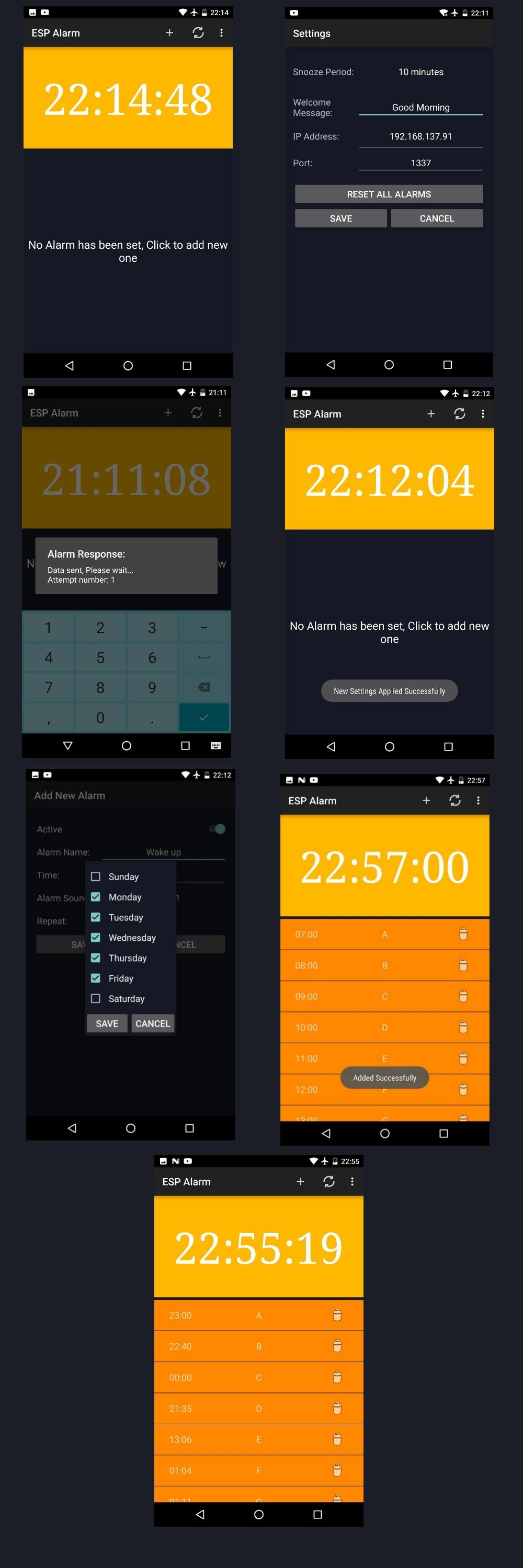
The Android application lets you control all the functionalities needed to add/edit/delete your specific alarms. It also gives you the ability to synchronize both date and time between the ESP Alarm and your mobile phone. The app has three major functions, explained below.


App Main Functions

We can divide our main functions into three areas.

First, we have the action bar where we have four buttons:

  • Add: To “Add” new alarms. We’ll go over this later.
  • Sync: To perform a date/time synchronization with the ESP Alarm.
  • Settings: To open the “Settings”. We’ll go over this later, too.
  • About: Displays a pop-up with info.

Second is the digital clock which displays the current time according to your phone’s settings 12/24 format.

Finally, the third function is the list of your pre-set alarms. This will, of course, be empty when the user runs the app for the first time. In this case, tapping inside this area will open the “Add Activity”. However, after adding alarms, this area will show the alarms’ time and title with a delete button for each alarm. If the user taps on any record, the app will launch the “Edit Activity”.


“Add” Function

Simply fill in your alarm’s title with the specific time. And don’t forget to activate the alarm!

You can choose the days you would like this alarm to be repeated by checking these days from the repeat days list.

Note that “Edit Activity” will allow the same changes. However, it will be automatically filled up with the selected alarm’s data.


“Settings” Function

  • The snooze period is limited to four options. The user must pick one of them.
  • The welcome message is optional for the user—but it is really awesome. For example, it allows the user to name his ESP Alarm, especially if he has more than one.
  • The user has to fill the IP address that is displayed on the ESP Alarm’s screen after it gets connected. The same goes for the port number.
  • “Reset all alarms” is a very critical button. Once the user clicks it, all alarms will be removed from the ESP Alarm and, if it gives back a reset response, then all alarms will be removed from the phone, too.

The best way to start using this app is:

  1. Go to settings and fill in the IP address and port fields.
  2. Press save. If you get a success message, then you’re on the right path.
  3. Press the sync button in the main activity to make sure your RTC has the right timing. This completes the initializing stage.
  4. You should now be able to start adding your alarms as you wish!

ATtiny84A from Arduino

I’m currently working on a project that requires a cheap, low-power microcontroller that’s programmable through Arduino and has a few more pins than the ATtiny85. That’s where I found the ATtiny84A. It has many of the same features as the ATtiny85, but has 12 I/O pins instead of six.

As it turns out, a lot of work has already been done to program ATtiny microcontrollers from Arduino, which makes this pretty easy. To start, connect an Arduino (UNO, etc.) to the ATtiny84A using the Arduino as ISP configuration. I’ll be using a 3.3V Arduino Pro Mini to keep everything nice and tidy on a breadboard.

Connect the Arduino to your computer, open the Arduino IDE and select File > Examples > 11.ArduinoISP > ArduinoISP.

Select your Board from Tools (Arduino Pro Mini 3.3V in this case), choose the serial port and upload the ISP sketch to the Arduino. Note that in this first step, we’re programming the Arduino to act as an in-system programmer (ISP), which we’ll use to send compiled programs to our target microcontroller (ATtiny84A).

Once you have uploaded the ISP sketch, place a 10μF capacitor across RESET and GND of the Arduino board (watch the polarity – for electrolytic and tantalum capacitors, make sure the side with negative markings, “-”, is connected to GND). Many Arduino boards are configured to reset when avrdude (the tool that Arduino uses to upload code to Atmel AVR microcontrollers) begins communication across the serial line. We can prevent that from happening by adding the capacitor.

At this point, we have the Arduino configured as a programmer for the ATtiny. Now, to program the ATtiny from the Arduino IDE, we need to include some custom board definitions. Luckily, GitHub user damellis has already created them for us (specifically for the ATtiny24/44/84 and ATtiny25/45/85). All we have to do is include them in our IDE.

In File > Preferences, paste the following URL into Additional Boards Manager URLs.

https://raw.githubusercontent.com/damellis/attiny/ide-1.6.x-boards-manager/package_damellis_attiny_index.json

In Tools > Board > Boards Manager…, search for “tiny” and install the attiny boards’ definitions.

We can finally write some code for the ATtiny! Open a new Arduino sketch and copy in the following. Note that we connected the LED to pin 13, which is PA0, and corresponds to D0 in Arduino code (see the pinout diagram below).

const int led = 0;

void setup() {
pinMode(led, OUTPUT);
}

void loop() {
digitalWrite(led, HIGH);
delay(500);
digitalWrite(led, LOW);
delay(500);
}

In case you were wondering how PA0 on the ATtiny84A matches with D0 on the Arduino, here is a diagram that will help:

Under Tools, select the following to make the ATtiny84A the target platform:

Board: ATtiny24/44/84
Processor: ATtiny84
Clock: Internal 1 MHz
Port: <The serial port attached to your Arduino>
Attiny84A as target board in Arduino

Upload the sketch, and you should be greeted by a beautiful blinking LED!

EXPLORING INTEL GALILEO

The list of official Arduino boards continues to grow, and, continuing with the famous-Italian-person trend, now includes the Galileo. The Galileo is Intel’s toe-dip into the Arduino waters. It features their Quark SoC X1000 – a 32-bit, x86 system-on-a-chip that can run at up to 400MHz with 512 kB of built-in SRAM.
The Galileo board supports the Quark with a wide range of external peripherals. There’s 8MB Flash (to store firmware), 11kB EEPROM, a µSD socket (supports up to 32GB), 10/100Mb Ethernet, USB 2.0 host and device ports, an RS-232 port, and a mini PCI Express (mPCIE) socket. On top of all that, it’s got that same, familiar Arduino pinout we all love (to hate?). The Arduino pins – including six analog inputs, SPI, I2C, UART, and PWM outputs – are all exactly where an Arduino user would expect them to be.

What the Galileo tries to do is meld the ease of Arduino’s hardware manipulation with the power of a Linux operating system. Most sketches written for Arduino Unos, Leonardos, and other boards can be ported directly over to the Galileo. You can still use popular Arduino libraries like SD, Ethernet, WiFi, EEPROM, SPI, and Wire, but you can also make requests of the Linux kernel with system() calls. This gives your Arduino sketch access to powerful utilities like Python, Node.js, OpenCV, and all sorts of fun Linux-y stuff.

Unread-Email-Checker Example Project

We were fortunate enough to receive a couple of early Galileo boards for evaluation, one of which landed in my hands to futz around with. To get a feel for the board, I tried to whip together a quick project that melded a few of the Galileo’s unique features together.

Most of our work communication occurs in emails, but I’m often turned away from my computer, wielding a soldering wand or banging my head against my Pi workstation as those emails pile up. It’s imperative that I stay up-to-date with the latest SparkFun memes and cool robot videos, so a simple unread-email-counter would be great to have permanently installed over my workbench. Sounds like a perfect project for the Galileo!

First, I needed a utility to check how many unread emails I have. Well, I don’t need much of an excuse to whip out some Python, so I did a quick search and found the script below. It logs into our email server with my credentials, checks how many unread emails there are in the inbox, and prints that value.

# pyMailCheck.py – Logs into your gmail and prints the number of unread emails.
# Place this file in the top level of your Galileo’s SD card.

import imaplib # Used to connect to an IMAP4 server.
obj = imaplib.IMAP4_SSL(‘imap.gmail.com’, ‘993’) # Connect to an IMAP4 sever over SSL, port 993
obj.login(‘my_email_address@gmail.com’,’myPassword’) # Identify the client user and password
obj.select() # Select a the ‘INBOX’ mailbox (default parameter)
# Search mailbox no (None) charset, criterion:”UnSeen”. Will return a tuple, grab the second part,
# split each string into a list, and return the length of that list:
print len(obj.search(None,’UnSeen’)[1][0].split())